A friend sent this link to me, and I immediately thought of Spikedriver our resident train expert. I thought it was really neat information. So simple in concept, but so functional. I did not know this about train wheels.
You are using an out of date browser. It may not display this or other websites correctly.
You should upgrade or use an alternative browser.
You should upgrade or use an alternative browser.
Interesting info on train wheel design
- Thread starter Haertig
- Start date
Help Support Homesteading & Country Living Forum:
This site may earn a commission from merchant affiliate
links, including eBay, Amazon, and others.
I'm glad they touched on that all important inner flange on the wheels.A friend sent this link to me, and I immediately thought of Spikedriver our resident train expert. I thought it was really neat information. So simple in concept, but so functional. I did not know this about train wheels.
If you have ever listened to train wheels go by in Alabama, you hear squeeeeek, squeaaal as they go over the unlevel tracks.
Visualize in their video what happens when one rail is 1 or 2 or 3 inches lower than the other rail.
The axle tilts and the wheel on the lower rail now has it's surface level with the rail, while the wheel on the 'now taller' rail, has a steep angle contact that tries to push the other wheel off the track.
The flange is the only thing that stops this and it makes a lot of noise.
I'm pretty sure 90% of @Spikedriver 's work is raising up rails that have 'sunk'.
*Disclaimer: I have worked on a lot of Trackmobiles in the past.
Last edited:
I wonder if they have any kind of sensors in the wheels to map out areas of the track with one side sunken? Maybe a thermal sensor (it's going to generate heat when the flange rubs on the rail). Or some way to detect sideways pressure on the flange. Or an optical sensor that detects the absence of a normal buffer space between the flange and the rail. Or an audible sensor that detects the screech of the flange rubbing. Then simply driving the train down the track could in theory generate a map on a computer that could indicate places with a sunken rail, indicating where repairs might be needed.
My mind had always imagined a trail wheel being like a pulley, with a deep U-channel in the middle. So you would effectively have a flange on both sides of the rail that would keep the wheel on the track. Like the roller on a sliding closet door. Obviously, I have never looked at a train wheel up close to know any better.
I find it fascinating learning things like this. Having been oblivious to the design in the past. I was reading in the comments for that video link that airplane wings are tilted upwards rather than flat for the same reason - to create a self centering force to help keep the plane from tilting side to side.
[edit]p.s. - Whadaya bet boat hulls are designed in a V shape for the same reason?![/edit]
Last edited:
I actually didn't know all that stuff. I don't actually have that much experience with trains and locomotives. I just work on the tracks to keep them safe for the trains.I'm glad they touched on that all important inner flange on the wheels.
If you have ever listened to train wheels go by in Alabama, you hear squeeeeek, squeaaal as they go over the unlevel tracks.
Visualize in their video what happens when one rail is 1 or 2 or 3 inches lower than the other rail.
The axle tilts and the wheel on the lower rail now has it's surface level with the rail, while the wheel on the 'now taller' rail, has a steep angle contact that tries to push the other wheel off the track.
The flange is the only thing that stops this and it makes a lot of noise.
I'm pretty sure 90% of @Spikedriver 's work is raising up rails that have 'sunk'.
*Disclaimer: I have worked on a lot of Trackmobiles in the past.
@Supervisor42 I have done a fair amount of work on tracks that have "sunk". I haven't done too much of that since 2013, but I spent much of 2011-2012 on a surfacing gang, or "surf gang" for short. Not only does a surf gang Rais the track, but also levels out humps, re-aligns curves and restores the proper amount of elevation to the high side of the track in those curves, and also straightens "tangent" track, which is a fancy word for "zero curvature". Tangent track will sometimes kick out to one side or the other in hot weather, or will gradually lose its perfect straight alignment over time. It's mostly done by million dollar machines with computers and lasers on them, but if need be I can go out there with a jack, a level, a shovel, and a tamping rod and restore proper elevation to the tracks. (Note: Doing that by yourself is not recommended! Even with 5 or 6 guys, it's hard damn work!)
There are special vehicles called Geometry Cars that do that work. I've never been in one but they can detect deviations from straight and level and also detect the force of impact when the wheels hit those spots that aren't level. Also there are track inspectors who run over the tracks at regular intervals to make sure things are as they should be. They do a lot of their work by eye and by feel. When something doesn't seem right, they have a whole raft of simple tools in their trucks like level boards to help them diagnose how good or bad the tracks are. It's a helluva lot of responsibility for a job that pays around $35/hour. In my home seniority district, there are 124 miles of mainline track and every inch of it has to be gone over not less than once every three days, per federal regulations. Plus there are the yard tracks and the industrial leads that must be inspected at least once every 30 days.I wonder if they have any kind of sensors in the wheels to map out areas of the track with one side sunken? Maybe a thermal sensor (it's going to generate heat when the flange rubs on the rail). Or some way to detect sideways pressure on the flange. Or an optical sensor that detects the absence of a normal buffer space between the flange and the rail. Or an audible sensor that detects the screech of the flange rubbing. Then simply driving the train down the track could in theory generate a map on a computer that could indicate places with a sunken rail, indicating where repairs might be needed.
My mind had always imagined a trail wheel being like a pulley, with a deep U-channel in the middle. So you would effectively have a flange on both sides of the rail that would keep the wheel on the track. Like the roller on a sliding closet door. Obviously, I have never looked at a train wheel up close to know any better.
I find it fascinating learning things like this. Having been oblivious to the design in the past. I was reading in the comments for that video link that airplane wings are tilted upwards rather than flat for the same reason - to create a self centering force to help keep the plane from tilting side to side.
[edit]p.s. - Whadaya bet boat hulls are designed in a V shape for the same reason?![/edit]
Well, don't come to Alabama!There are special vehicles called Geometry Cars that do that work. I've never been in one but they can detect deviations from straight and level and also detect the force of impact when the wheels hit those spots that aren't level. Also there are track inspectors who run over the tracks at regular intervals to make sure things are as they should be. They do a lot of their work by eye and by feel. When something doesn't seem right, they have a whole raft of simple tools in their trucks like level boards to help them diagnose how good or bad the tracks are. It's a helluva lot of responsibility for a job that pays around $35/hour. In my home seniority district, there are 124 miles of mainline track and every inch of it has to be gone over not less than once every three days, per federal regulations. Plus there are the yard tracks and the industrial leads that must be inspected at least once every 30 days.

They will give you guys lots of work!
Try to find your 'Federal regulations' here:
Or maybe here?
Last edited:
That is known as "Federally Excepted Rail". The Federal Rail standards for excepted Rail are, shall we say, quite loose? Basically, if the tracks don't fall apart under the weight of the train and the geometry of the tracks is good enough to keep the train from falling off the rails, it should be OK. There are some standards, like there must be at least 5 good ties in any 39 foot section of track, and said ties must be distributed within that 39 feet such that the distance between the rails never exceeds 57 3/4". And trains on such track may never exceed 10mph.Well, don't come to Alabama!
They will give you guys lots of work!
Try to find your Federal regulations here:
Or maybe here?
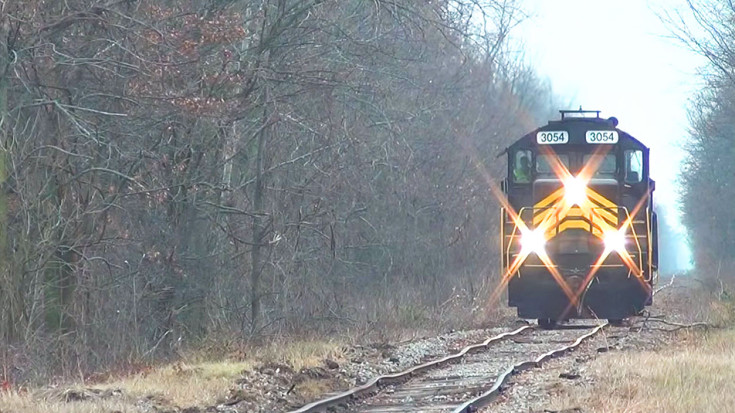
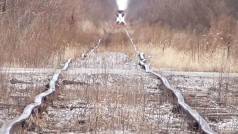
I would guess that the locomotive in the picture would not want to exceed 5 mph. It's pretty rare to ever see track that bad.
I'm wondering why anyone would want to drive a train down that track in the first place. What would be the point? (maybe to set a Guinness World Record?)I would guess that the locomotive in the picture would not want to exceed 5 mph. It's pretty rare to ever see track that bad.
That picture gives me even more respect for those self-centering wheels!
Lol that engineer probably doesn't want to ride that rail. He's only doing it because he's getting paid well to do it. And if he derails and he wasn't violating any rules when it happened, he's not going to get into trouble for it.I'm wondering why anyone would want to drive a train down that track in the first place. What would be the point? (maybe to set a Guinness World Record?)
That picture gives me even more respect for those self-centering wheels!
I am guessing there is some crappy business like an old lumberyard or an animal byproduct factory at the end of those tracks, and they only get used a couple times a month. There is an industrial lead back home that maybe sees 4 trains a year, and the inspector gets nervous when they use it. I just saw part of it last summer. It looks better that the track in the photo, but not much better...
- Joined
- Sep 4, 2020
- Messages
- 9,454
While I did not work with the design engineers for the wheels I did work with production engineering.
After I helped to fix a nagging problem with an ultrasonic inspection station in Spain they let me take some pictures.


Lots of big CNC machines but what surprised me was the wheels were pressed on to the axles with giant hydraulic presses.
The ultrasonic inspection checked for voids in the finished wheels. Voids in the tread or hub triggered rejections of the wheel.
The attached pdf discusses a novel method of "seeing" the flaws in a 3d model of the wheel for a factory in China.
Fun times but I still prefer retirement.
Ben
After I helped to fix a nagging problem with an ultrasonic inspection station in Spain they let me take some pictures.
Lots of big CNC machines but what surprised me was the wheels were pressed on to the axles with giant hydraulic presses.
The ultrasonic inspection checked for voids in the finished wheels. Voids in the tread or hub triggered rejections of the wheel.
The attached pdf discusses a novel method of "seeing" the flaws in a 3d model of the wheel for a factory in China.
Fun times but I still prefer retirement.
Ben